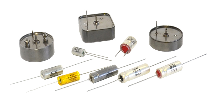
Green Tech makes series high reliability tantalum capacitors,Include SMD type, dipped type, axial leads type.Solid and wet type, industrial and military standard.High temperature type, high energy hybrid type etc.
1. Short Summary of The Manufactruring Process
1.1 Moulding
Press high purity tantalum power and tantalum wire together into the basic unit of tantalum pellet.
1.2 Sintering
Put the tantalum pellets in vacuum at high temperature to sinter the tantalum power
1.3 Engergization
Put the tantalum pellets in the electrolyte, connect the tantalum pellets with anode and the electrolytic with cathode, power with a current and a tantalum pentoxide film is electrochemically formed on the surface.
MnO2 or Conductive Polymer Generation: Dip the tantalum pellets in a Mn(NO3)2 solution, decompose the Mn(NO3)2 into MnO2 under 250℃~300℃. Repeat this process to let the MnO2 fill the pores of the tantalum particles. Or generate conductive polymer by the chemical reaction of thipphene and oxidizer.
1.4 Packaging
According to different package, different types of tantalum capacitor be installed.
1.5 Burn-in
Remove early waste by loading voltages and improving temperatures.
1.6 Testing
All products must past the parameters's test.
2. Basic Instructions
2.1 The capacitance is expressed by nominal capacitance(CR), the unit is μF. To avoid the impact of power frequency, measured by 100Hz or 120Hz using the equivalent circuit in series, the standard measuring voltage U_=2.20-1.0V, U~=1.00-0.5V(RMS) or lower. temperature 25℃, allowed to float within a range of 15℃~35℃.
2.2 Capacitance Tolerance
It means the permissible error to the nominal capacitance value.
J=±5%, K=±10%, M=±20%, Q=—10%~+30%
2.3 Loss Tangent(tgδ)
Because of resistance caused by capacitor structure, in series equivalent circuit, the loss can be stated by the electrical equipment's response to frequency Xc=1/2πfc and equivalent series resistance, be tgδ=ESR/Xc, and the loss tangent is measured under 0.5VAC 120Hz and changed into percentage.
2.4 Rated Voltage.
It is the maximum DC voltage that can continuously applied on the capacitor, termed by VRUR and the unit: Volt(V).
2.5 Leakage Current
Measured in series with 1KΩ,after 5min under rated voltage, and the standard leakage current is not more than the result of capacitance by rated voltage by a constant.
2.6 Equivalent Series Resistance (ESR)
It is the resistance measured in series equivalent current, under a frequency of 100KHz.
2.7 Temperature Range
The temperature range is -55℃~125℃,the maximum temperature is +85℃ under rated voltage, the derated voltage is used when the maximum allowable applied voltage above +85℃, specified in the instructions of each model. The derated voltage is 0.65 times of the rated voltage.
3. Operate Instructions.
3.1 Operating Temperature
The raged of working voltage and rated voltage has a great impact on the breakdown of capacitors, so please appropriate reduce the voltage regarding all requirements to reliability when designing the actual circuit.
In low impedance circuit (especial filter capacitors in the switching power supply), please set the working voltage below 1/3 of the rated voltage. In other case, please set the working voltage below 2/3 of the rated voltage.
When paralleled in low impedance circuit, the failure risk of DC surge current will increase, and also notice the stored charge can discharges through other capacitors.
To control the momentary high-current impcact on the capacitor in the circuit, it's better choice to have a resistor above 3Ω/V in series to limit the current below 300mA. When the protective resistor is unable, please use 1/3 the rated voltage as working voltage.
3.2 Reverse Voltage
Solid tantalum is polarized, reverse voltage application is not permit in generally. In worst case, a small reverse voltage is permit but it can not more than 10% of UR or V(whichever is smaller) at 25℃.
In the circuit with long-term reverse voltage, un-polarized capacitors have priority. Silver case wet tantalum capacitors like CA30 and CA35 can not withstand reverse voltage, they must be scraped if any reverse voltage was accidentally applied on them in the measurement process even if the parameters in the process are qualified.
All tantalum case wet tantalum capacitor like CAK39, CAK39h, CAK38 etc. can load 3V reverse voltage. Tantalum capacitor can not measured by multimeter's resistance file regardless of the polarity.
3.3 Factors Affecting Of The Failure Rate
The more lower working voltage than rated voltage load on the poles, the more lower failure rate of tantalum capacitor. The failure rate is measured on the maximum allowable load under rated voltage at 85℃, but usually there are surge voltage or surge current and ripple current in actual circuit. To use tantalum capactiors on high reliability, the recommended voltage is 1/2 of the rated voltage. In the case of above 85℃, at a step-down design based on derated voltage is neccessary, and the derated voltage is 0.65 times of the rated voltage. Another factor affecting the failure rate is the series resistance, the more higher series resistance in the circuit the more lower failure rate.
Failure rate grade : 2.0%/1000h represented as L, 1.0%/1000h represented as M, 0.1%/1000h represented as P, 0.01%/1000h represented as R, 0.001%/1000h represented as S.
3.4 Ripple Current
The sum of DC bias and AC voltage peak can not exceed the rated voltage of the capacitor, and the sum of negative AV voltage peak and DC bias can not exceed the reverse voltage of the capacitor.
Ripple current cause an internal temperature rise due to the active power loss when current through the capacitor and increase the probability of thermal breakdown, so it is necessary to limit the ripple current and active power loss in the capacitor.
The following table 1 is the effective value of maximum ripple current of variety of wet tantalum capacitors by case, while table 2 is the ripple current factor under different voltage and frequency.
Table 1 The Effective Value Of Maximum Ripple Current Of Non-solid Tantalum Capacitors by Case
| Case | 0 | 1 | 2 | 3 | 4 | 5 | 6 | 7 | 8 |
| I rms(mA) | 40 | 50 | 105 | 280 | 380 | 500 | 600 | 750 | 850 |
Table 2 The Ripple Current Coefficient
Frequency
Temperature(℃)
Working Voltage
UR
0.9UR
0.8UR
0.7UR
0.66UR
120Hz
<55
Coefficient
0.60
0.60
0.60
0.60
0.60
85
0.39
0.46
0.52
0.58
0.60
105
-
-
0.35
0.44
0.46
125
-
-
-
-
0.27
800Hz
<55
0.71
0.71
0.71
0.71
0.71
85
0.43
0.55
0.62
0.69
0.71
105
-
-
0.42
0.52
0.55
125
-
-
-
-
0.32
1KHz
<55
0.72
0.72
0.72
0.72
0.72
85
0.45
0.55
0.62
0.70
0.72
105
-
-
0.42
0.52
0.55
125
-
-
-
-
0.32
10KHz
<55
0.88
0.88
0.88
0.88
0.88
85
0.55
0.67
0.76
0.85
0.88
105
-
-
0.52
0.64
0.68
125
-
-
-
-
0.40
40KHz
<55
1.0
1.0
1.0
1.0
1.0
85
0.63
0.77
0.87
0.97
1.0
105
-
-
0.59
0.73
0.77
125
-
--
-
-
0.45
100KHz
<55
1.1
1.1
1.1
1.1
1.1
85
0.69
0.85
0.95
0.07
1.1
105
-
-
0.65
0.80
0.85
125
-
-
-
-
0.5
Note: The capacitor's power loss limit (Pactive) is depends on its heat dissipation conditions, like geometric size, the thermal conductivity, enviromental conditions, etc. When on complete appliacne packaging and needed high reliability , please consider derating design.
3.5 Operating Temperature
Please use the capacitor within the operating temperature range prescribed. Above 85℃, please use derated voltage as working voltage. Temperature characteristic is one of the main electrical characteristics of tantalum capacitor, so when there is great temperature variation, please verify the circuit characteristics within the upper and lower limits.
3.6 Reliability
The failure rate of tantalum capacitors vary to different working conditions(Temperature, Load Voltage, Circuit Resistance, Circuit, etc.), so please select suitable product after carefully reading the instructions.
1) When designed, it was based on the failure rate of 1000h under rated voltage at 80℃, but considering the impacts of surge voltage, surge current, ripple current and other impacts in actual use, so derating design is necessary. And 65% of UR(Rated Voltage) is suggested.
2)In safety equipment, to avoid short circuit and open circuit, please notice the following:
-Design protection circuit to protect devices and system to insure safety.
-Designing redundant circuit, make sure the whole system can operate normal even single fault.
3.7 When Detecting Leaks Using PH Test Paper
The wet electrolytic tantalum capacitors should be fully discharged, otherwise affect by the two pole's charges, the positive charges make the OH— in the paper lose charges and excess H+ cause color change and thus have false judgment.
4 Installations
When installed in the PCB, if load by overlarge mechanical shock or heat shock, the electrical charateristics will be deteriorated, open circuit, short circuit, etc. So please confirm these installation conditions before action.
4.1 Use and Measurement
1) Please no excessive force, in case plating layer on the capacitor or leads terminal peel.
2) No use the capacitors that have been installed once or dropped.
3) No hand-only touch with capacitor leads (including terminals of chip tantalum capacitors) in the process of use and measurement in case of bad soldering caused by sweat and oiltain.
4.2 Circuit Board Cleaning
When cleaning the circuit board, besides flux, please also quickly clear acid and alkali to make sure no residue, the temperature below 50℃ and the total time under ultrasonic and steam within 5mins. Please also note that ultrasonic may fracture the terminal in certain conditions.
4.3Soldering
By electric iron(<30W), the temperature of solder tip shall be below 350℃, time be within 4s, and no touch with the capacitor body.
To chip tantalum capacitors, no use of flux with high activity and strong acid whatever hand doldering or reflow soldering, in case its side-effect or infiltration, corrosion, diffusion on reliability.
To circuit boards with different types, different sizes and different component mounting density, there be different temperatures can be applied on these components.
Folow soldring and reflection welding can be applied to chip tantalum capacitors, but must under the following conditons:
Wave Soldering
Fixed the components with adhesive on the circuit, then directly immerse in the soldering pot.
Note: High component mounting density can reduce solderability, so please pay attention to put in gas.
Preheating should be below 160℃, within 2 minutes, and please cooling slowly after soldering.
Reflow Soldering
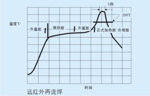
Temperature curves reference as following:
Warming part/ Normal temperature preheating part 30s~60s Preheating part 140℃~160℃ 60s~120s
Warming part/Preheating 200℃ 20s~40sformal heating Peak 5s(as figures below)
Cooling part between 200℃~100℃ 1℃~4℃/S

By hot-plate soldering or vapor-phase soldering or other method, please contact with us.
5. Operating Environment and Storage
5.1 No use in the following environments
Direct touch with water, salt, oil, etc.
Direct exposed under solar radiation
High temperature, high humidity, surface condensation
With reactive gases
With acid, alkali
With high-frequency electromagnetic induction
With excessive vibration or strike
5.2 Maintenace and Measurement
When detectin the capacitor by instrument, please check the equipment's potential and polarity, in case of short circuit by load reverse voltage. Also make sure there is not touch with other component terminal when detecting, and not allow bend the capacitor.
5.3 Malfuction
If reeking or fuming after power, cut the power immediately. If burning, do not touch with hands or face. In short circuit, encapsulation resin may smoke and tantalum pellets may catch fire.
5.4 Storage
In principle, store period is 10 years after manufactured (Expect the solderability)
Please store the capacitor in regular package. Do not exposed under sunlight or dust. In especial normal temperature(-10℃~40℃)and normal humidity(below 80% RH).
For long-term storage at the normal temperature and humidity, all the solderability and the capacitor's performance will drop.


